Welcome to Sonic Buster 8 home page!
 Sonic Buster 8 review on YouTube by root42
Sonic Buster 8 review on Retronautics by appiah4
Sonic Buster 8 thread on VOGONS.ORG
Latest firmware version is 4.01
![]() Overview
Overview
![]() Features
Features
![]() Configuration
Configuration
![]() PC-Speaker input
PC-Speaker input
![]() CD/Aux audio input
CD/Aux audio input
![]() Volume controls
Volume controls
![]() Audio output
Audio output
![]() Firmware updates
Firmware updates
![]() New DSP functions
New DSP functions
![]() Photo gallery
Photo gallery

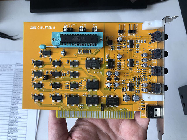
Overview
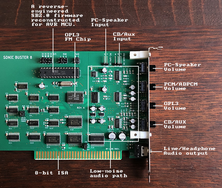
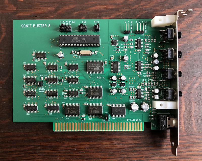
Sonic Buster 8 is a modern ISA sound card designed for IBM PC XT (8086/8088), AT (286, 386, 486, Pentium), and compatible computers. It is built for retro-gaming in DOS and early Windows environments. The card is straightforward to use and is fully software compatible with the golden standard of DOS gaming - the Sound Blaster 2.0.
Its firmware is based on a reverse-engineered SB 2.0 DSP firmware written entirely from scratch for an AVR MCU, implementing all the internal workings and timings of the original hardware. However, while remaining fully playback-compatible with the Sound Blaster 2.0, Sonic Buster 8 also surpasses it in several key ways.
The card integrates a high-quality, ultra-quiet analog path that drastically reduces the background hiss and digital noise the original Sound Blaster line is famous for. It also employs a 2-stage active low-pass filter to minimize the harsh aliasing effects of 8-bit sound while carefully preserving high-frequency clarity. This results in a much cleaner, more pronounced audio output.
For games with CD music, Sonic Buster 8 features an internal stereo CD/Aux input header with a dedicated volume control on the back panel. This can also be used to connect any line-level audio source, such as an external MIDI sound module or the output from another sound card in the system.
For vintage games that only support PC Speaker audio, Sonic Buster 8 includes an internal PC Speaker input with a dedicated back-panel volume control. The audio path features an active low-pass filter to round out the harsh beeper waves, making the sound more pleasant to the ear.
Unlike the original Sound Blaster, Sonic Buster 8 features a physical analog mixer with four dedicated volume potentiometers accessible on the back bracket for all sound sources: PCM/ADPCM digital audio, FM music, CD/Aux, and the PC Speaker.
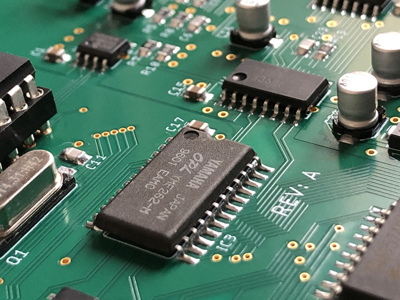
Finally, it upgrades the FM synthesis hardware by utilizing a more advanced Yamaha OPL3 chip instead of the older OPL2.
Features
-
Fully compatible with Sound Blaster 2.0 8-bit audio. PCM and ADPCM mono digital audio playback. Supports PCM playback rates up to 62,500 Hz. Offers new, proprietary SB8-specific DSP functions for future homebrew retro software.
-
Yamaha OPL3 FM Synthesis: Uses a genuine OPL3 chip instead of an OPL2 for FM music playback. The OPL3 is fully backward-compatible with the OPL2 and sounds identical in older titles, but unlocks advanced 4-OP music in games that support it. Crucially, unlike the OPL2, it avoids a lot of timing problems on machines faster than a 386. For example, on a 486, Prince of Persia plays beautifully on Sonic Buster 8, whereas an original OPL2 board often outputs chaotic noise.
-
CD/Aux Stereo Input: Internal header for connecting CD-ROM analog audio or any other auxiliary sound source, such as a MIDI sound module.
-
PC Speaker Input: Internal header to route classic motherboard beeper sounds directly into the card’s audio output instead of a case speaker—perfect for ancient games.
-
Ultra-Quiet Analog Path (around -100dB RMS): Delivers a clean sound, entirely eliminating classic Sound Blaster background hum and interference.
-
In-System Upgradable: Firmware can be flashed and updated directly from the DOS command line.
-
Independent Clocking: Works perfectly on motherboards that lack a native 14.32MHz OSC clock on the ISA bus, which was a hard requirement for the original Sound Blaster.
-
No -5V Power Rail Required: Operates entirely off standard +5V and +/-12V lines, resolving compatibility issues with modern or ATX replacement power supplies that omit the legacy -5V rail.
-
Bus Flexibility: Fully tested and stable across 6 MHz, 8 MHz, and 12 MHz ISA bus speeds.
-
Selectable Adlib Addressing: Allows the user to completely disable Adlib functionality on port 388h via an onboard jumper. If you have an orignal Adlib in your rig as well and want use it instead.
Configuration
System Requirements 
IBM PC XT / AT 286, 386, 486 or Pentium or compatible system with one free 8-bit or 16-bit ISA slot.
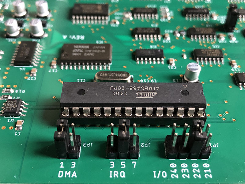
Hardware Settings
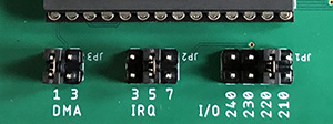
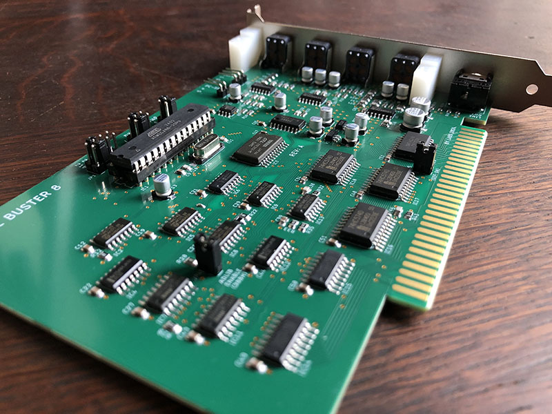
Hardware configuration is handled entirely via physical jumpers to select the I/O port, IRQ, and DMA channel using JP1, JP2, and JP3 respectively.
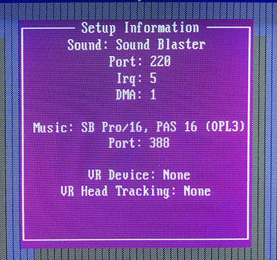
The most common configuration is 220h for I/O port, 5 for IRQ and 1 for DMA:
Always ensure the computer is powered off before adjusting any jumper settings.
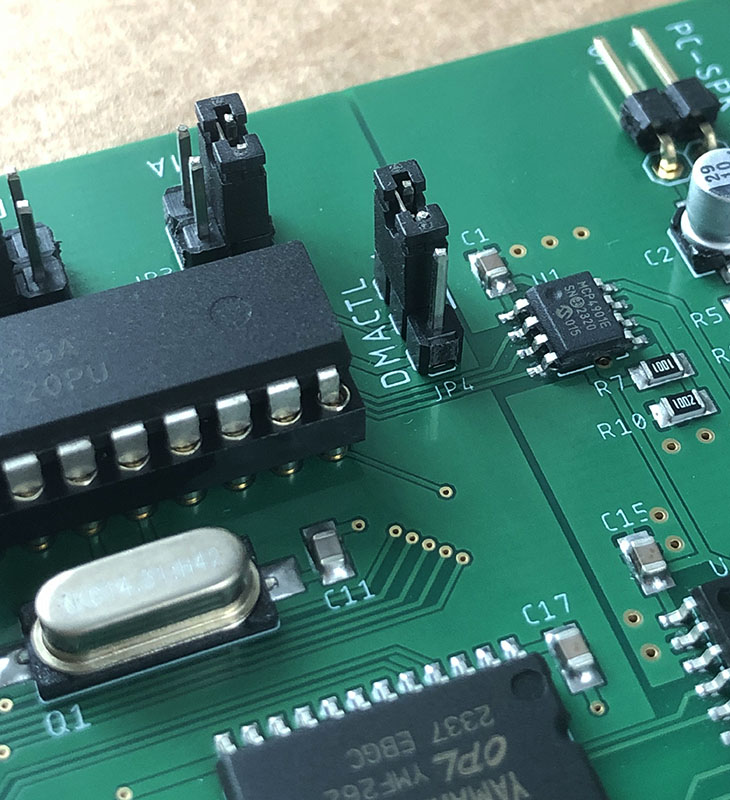
DMACTL Jumper
This jumper enables or disables the sharing of the selected DMA channel (JP2) with the rest of the system. It is included strictly for architectural compatibility with original SB 2.0 hardware quirks. It should remain in its default state unless your specific environment requires DMA channel sharing (which is highly unlikely and generally not recommended).
| JP4 | |
|---|---|
| 1-2 | DMA sharing is disabled (default) |
| 2-3 | DMA sharing is enabled |
(Note: This jumper is not present on REV-A boards).
ADLIBEN (Adlib Enable) Jumper
This feature was added for users who run a dedicated standalone Adlib card alongside the Sonic Buster 8, and want the original Adlib card to handle FM music whenever “Adlib (388h)” is selected in a game’s audio setup.
| JP5 | |
|---|---|
| CLOSE | Port 388h is activated (default) |
| OPEN | Port 388h is inactive |
This jumper should remain closed for normal operation. When opened, the internal OPL3 chip is disconnected from the standard Adlib port (388h), but will continue to function normally on the 2x0h-2x3h and 2x8h/2x9h base address ports.
(Note: This is labeled JP4 on REV-A boards).
RESET Jumper
This jumper selects the card’s bus reset circuit mode.
By default, Sonic Buster 8 is engineered to be much more tolerant of fast 486 and Pentium systems than an original SB 2.0 card. Certain picky games and demos can run successfully with the Sonic Buster 8 where an original Sound Blaster would completely fail (such as the Crystal demo, Prince of Persia, Alone in the Dark in DMA mode, etc).
However, an alternative reset circuit is provided as an additional option:
| JP6 | |
|---|---|
| 1-2 | SB 2.0 reset mode (default) |
| 2-3 | IORDY reset mode |
It is recommended to keep this jumper in SB 2.0 mode by default. If you run into problematic software on a fast machine, you can try switching it to IORDY mode to see how it behaves on your specific motherboard. The idea of this mode is — when selected, it pulls the ISA bus IORDY line to GND during a DSP RESET command to insert hardware wait states. This is useful because many older games use a simple program loop to wait for the sound card to reset, but fast CPUs run through these loops too quickly, causing the game to assume the reset failed before the card can even respond. Pulling IORDY low pauses the CPU, trying to keep the expected wait loop from expiring too fast and possibly helping to initialize the card successfully.
Please note that IORDY mode is not universally compatible. For example, the game Gods will not produce PCM sound when IORDY reset mode is selected. Conversely, initialization routines in Build engine games (such as Duke Nukem 3D, Blood, and Redneck Rampage) are much snappier in this mode than on a real SB 2.0.
On REV-A cards, this feature is controlled by a 2-pin jumper named BUSHLD:
| JP5 | |
|---|---|
| OPEN | SB 2.0 reset mode (default) |
| CLOSE | IORDY reset mode |
DOS Configuration
To inform your DOS software which hardware resources the card is using, you must set the standard BLASTER environment variable. This is typically done by adding the initialization string to your C:\AUTOEXEC.BAT file.
For the standard configuration pictured above, the string is:
SET BLASTER = A220 I5 D1 T3
Where:
Axxx – I/O address (210/220/230/240)
Ix – IRQ number (3/5/7)
Dx – 8-bit DMA setting (1/3)
Tx – Sound Blaster architecture type (where 3 specifies an SB 2.0, which applies to Sonic Buster 8)
Game Configuration
To use Sonic Buster 8 in games, simply open the game’s setup utility and select Sound Blaster version 2.0 (or earlier/compatible).
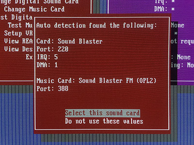
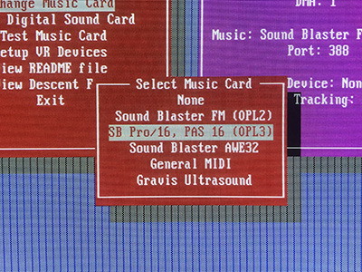
Even if the Music Card (above) is automatically detected as Sound Blaster FM (OPL2), you can manually select OPL3 in games that explicitly support it (below).
Windows 9x/ME configuration
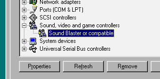
Windows 95, 98, and ME will automatically detect Sonic Buster 8 as a standard Sound Blaster or compatible device either during OS installation or after running the Add New Hardware wizard in the Control Panel:
Internal Audio Headers
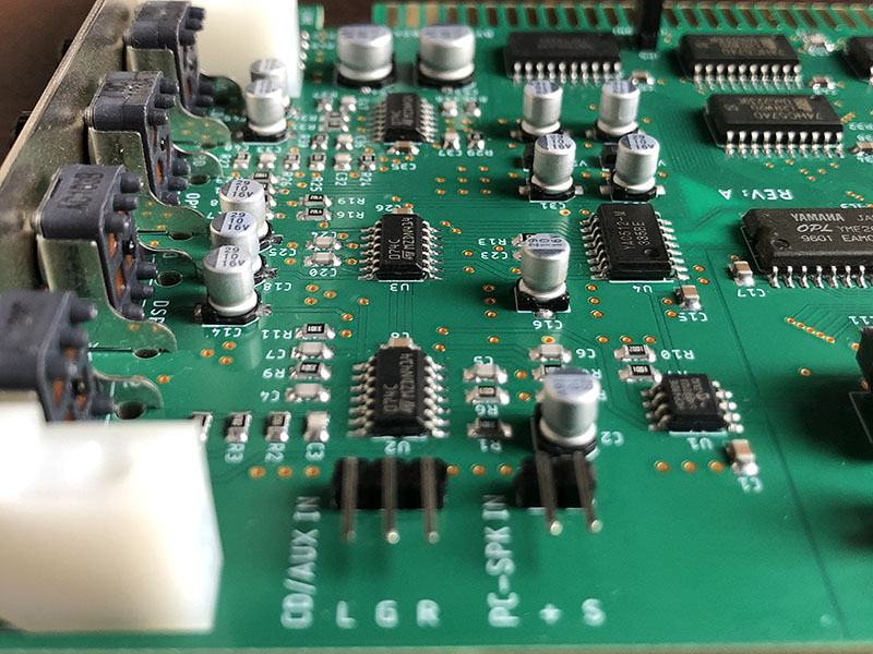
 PC Speaker Input
This input is designed to catch audio from older games that do not support dedicated sound cards and only output via the PC system beeper. The internal analog path features an active low-pass filter to round out the harsh beeps, making them a bit more pleasant to the ears.
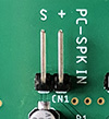
The signal from the motherboard’s speaker header should be routed here. The 4-pin header on a motherboard is typically marked as SPK, SPEAKER, or SPKR. Generally, only the two outermost pins matter: one is usually labeled VCC, SPEAK+, or simply +, while the other is typically SPEAK- or ground.
Using the included 2-pin cable, connect the positive pin to the + pin on the card, and the other pin to the S pin. If no PC speaker sound is audible, check the dedicated gain pot on the back panel or try reversing the orientation of the 2-pin connector.
 CD/Aux Input
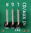
This input accepts a standard line-level stereo analog signal. The pinout is explicitly marked on the PCB layout as L (Left), G (Ground), and R (Right).
Using the included 3-pin cable, you can connect the analog audio output of a CD-ROM drive directly to this header. It can also be used to route internal audio from other sound hardware, such as a MIDI sound module or a secondary sound card. Volume levels can be adjusted using the corresponding potentiometer on the card’s bracket (see below).
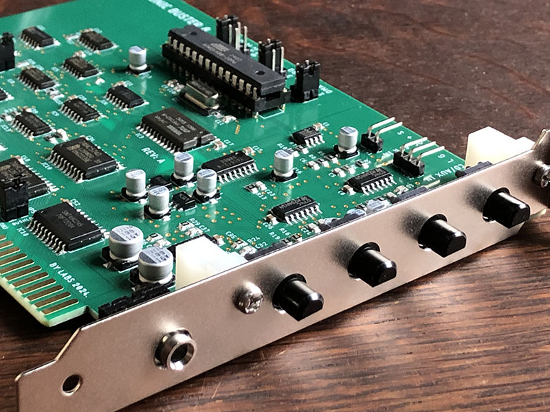
Manual Volume Controls
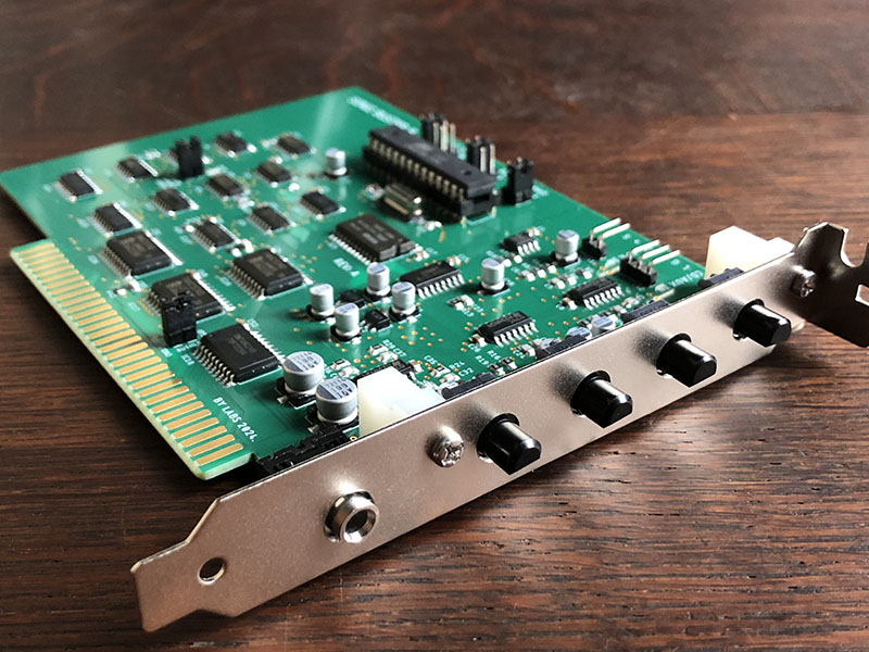
The back bracket contains four analog potentiometers to adjust volume levels for PCM/ADPCM digital audio, FM music, PC Speaker, and CD/Aux:
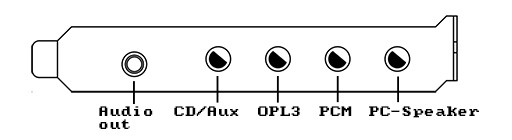
After connecting the card’s output to an external amplifier or powered desktop speakers, it is recommended to turn the OPL3 volume knob to maximum (fully clockwise) and balance the remaining three dials relative to it to set the proper volume levels. Because the OPL3 chip can sum up to 18 music channels simultaneously, its output stage is designed with extra headroom to prevent clipping during busy musical passages. As a result, its nominal output level may seem quieter than the other sources on the card.
Audio Output
The onboard low-noise analog mixer routes to a 3.5mm stereo mini-jack output. It is capable of driving line-level inputs on external audio systems, or powering standard headphones directly.
Firmware Updates
Download  SB8VER.ZIP utility to verify the current firmware version running on your Sonic Buster 8 card.
SB8FW401.ZIP - Sonic Buster 8 firmware v4.01.
This firmware update fixes DMA timing issues found on some motherboards and is recommended for all users.
To update, extract the contents of the archive to a dedicated directory in DOS, run SB8FLASH.EXE, and follow the on-screen prompts.
New DSP Functions
For developers writing new DOS software or homebrew games who want to target Sonic Buster 8 capabilities directly, the card introduces several custom extensions to the classic Sound Blaster command set.
Detecting Sonic Buster 8
Command E5h checks if Sonic Buster 8 is present and reads its firmware version.
- Command Byte:
E5h - Execution: After sending command
E5hto the DSP Write port, read back exactly two consecutive bytes from the DSP Read port. The first byte returned represents the major version number, and the second byte represents the minor version number. For the Sonic Buster 8, the major version byte will always be4. - Behavior: If both bytes are read successfully from the data port without timing out, a Sonic Buster 8 card is present in the machine. Your application can then safely utilize its OPL3 chip or secondary DSP extensions. If the read loop times out - Sonic Buster 8 is not present in the system.
Setting 16-bit Time Constant
Thanks to the MCU’s 16-bit hardware timer, the Sonic Buster 8 supports a precise 16-bit time constant for digital playback. This yields more accurate sample rates than the original Sound Blaster could achieve using standard command 40h. To support this, the Sonic Buster 8 firmware provides two additional DSP commands (50h and 51h) described below.
This table illustrates the real-world sample rate accuracy achieved using legacy Sound Blaster command 40h versus the Sonic Buster 8 time constant methods:
+--------------------------------------------+
| Requested | Real rate,  | Real rate, SB8   |
| rate, Hz  | cmd 40h, Hz | cmds 50h/51h, Hz |
| --------- | ----------- | ---------------- |
| 11025     | 11111       | 11030            |
| 22050     | 22222       | 22061            |
| 32768     | 33333       | 32764            |
| 44100     | 45454       | 44055            |
+--------------------------------------------+
The programming sequence is as follows:
- Query the hardware clock constant from the DSP using command
50h. - Compute the precise time constant in your software.
- Write the 16-bit integer result back to the DSP using command
51h.
1. Read DSP Clock Constant (50h)
- Command Byte:
50h - Execution: Send command
50h, then read back 4 consecutive bytes from the DSP data port. These 4 bytes combine to form a single, unsigned 32-bit integer representing the card’s exact master clock speed in Hz. - Byte Ordering: The bytes are streamed in Big-Endian format:
Byte 1: Bits 31-24 (Most Significant Byte)
Byte 2: Bits 23-16
Byte 3: Bits 15-8
Byte 4: Bits 7-0 (Least Significant Byte)
This 32-bit value is a constant for the specific Sonic Buster 8 card and only needs to be read once during initialization. However, the value can differ between different card models and revisions.
After reading the clock constant, we calculate a time constant as our next step.
2. Calculate 16-bit Time Constant
Time constant calculation for a target playback rate is made using this formula:
time_constant = dsp_clock_constant / playback_rate
The result should be rounded to the closest 2-byte integer value and sent back to the DSP using command 51h.
Example:
If command `50h` returned a clock constant of `14,318,181` Hz and your program requires a playback rate of 44,100 Hz:

time_constant = 14318181 / 44100 = 324.675 (Rounds to 325)

So we need to write `325` to the DSP to set the time constant.
3. Write Time Constant (51h)
- Command Sequence:
51h,time_constant.HighByte,time_constant.LowByte - Execution: After calculating the integer time constant, write the 2-byte result to the DSP data port.
The byte sequence must be:
- Send command byte
51h - Send
time_constantHigh Byte (Bits 15-8) - Send
time_constantLow Byte (Bits 7-0)
Once this is done, standard DMA playback modes can be safely initiated.
Time Constant Precision
For the example above, we can check the precision of the actual playback rate achieved by the DSP internal timer like this:
14318181 / 325 = 44055 Hz
By comparison, configuring a standard Sound Blaster card for 44,100 Hz using the legacy legacy command 40h results in an actual hardware playback speed of 45,454 Hz—introducing a noticeable sample rate error.
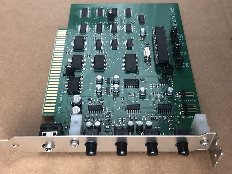
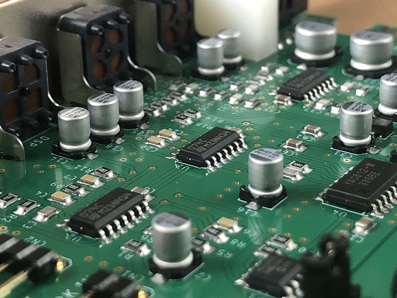
Photo gallery
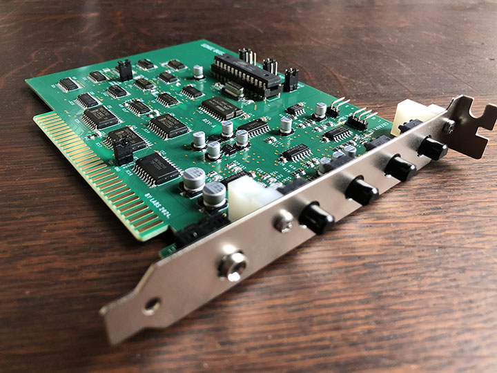
REV-B:
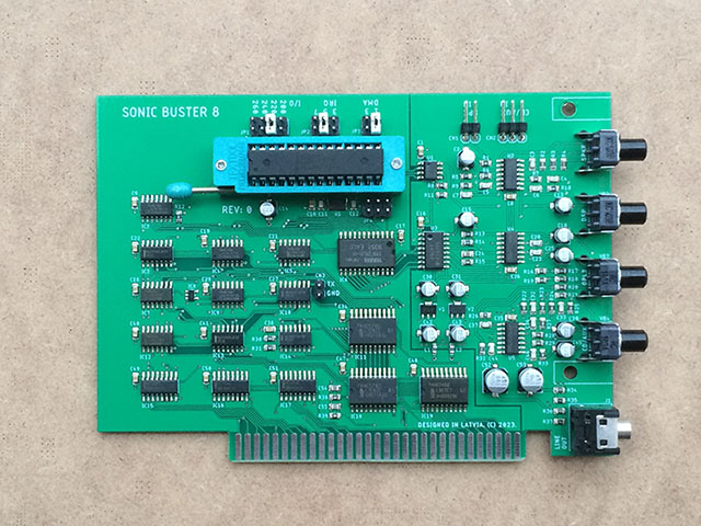
REV-A:
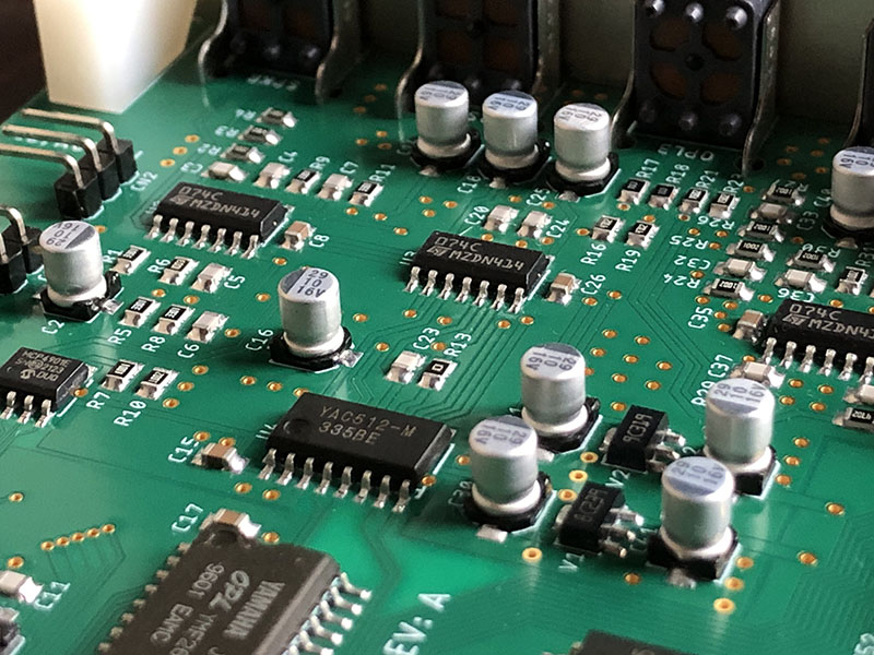
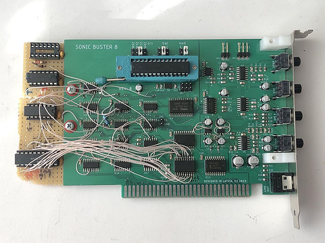
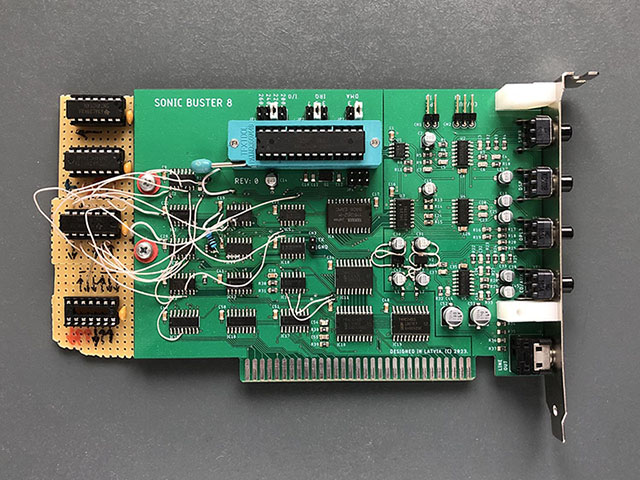
Prototype #2:
Prototype #1: